BASIC CARBURETOR SYSTEMS
The carburetor performs a comparatively simple job but it does so under such varied conditions that it is necessary to have several systems to alter its functions so that it can adjust to various situations. Most carburetors contain the following six basic systems:
- Float System
- Idle System
- Main Metering System
- Power System
- Pump System
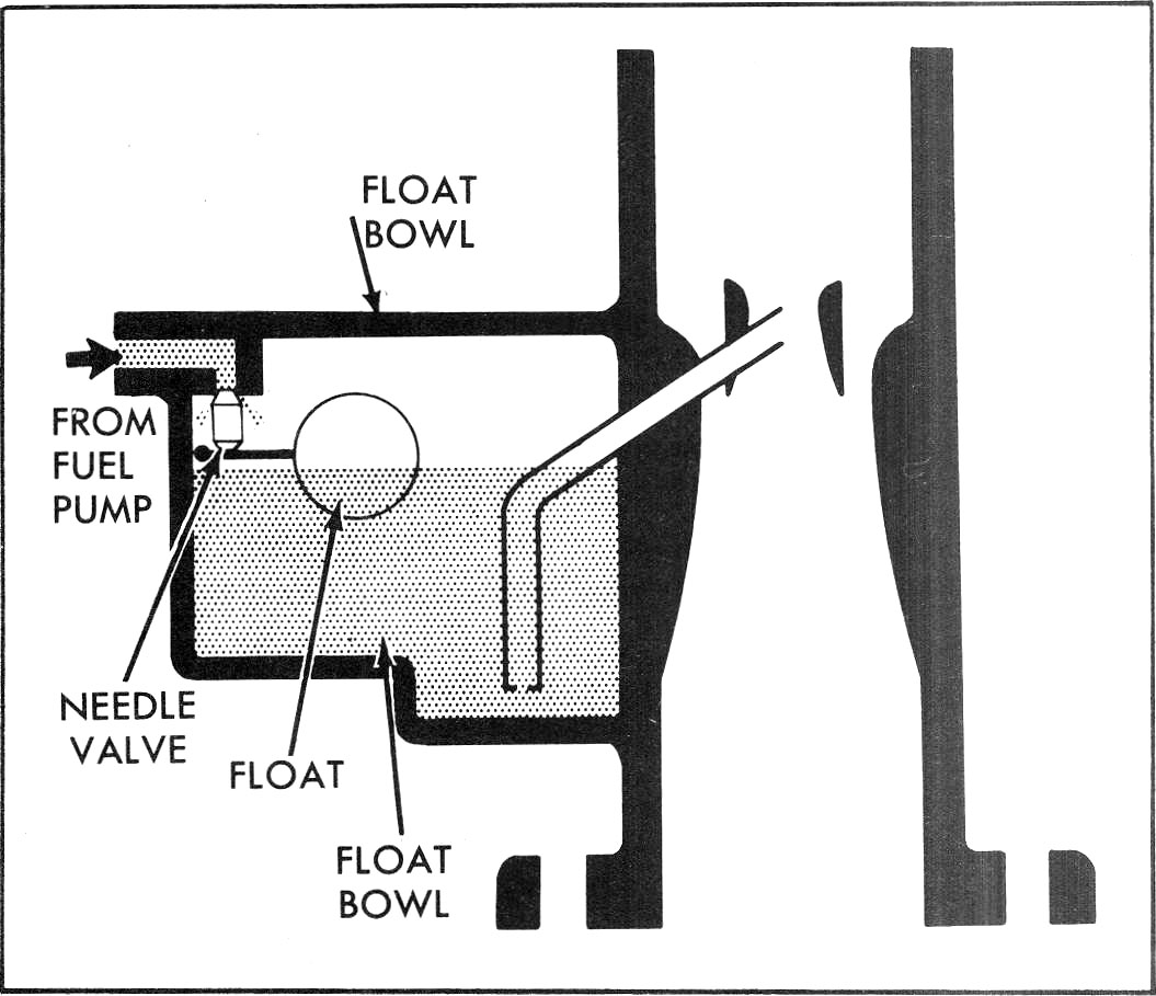
Float System (Fig. 14)
Fuel in the carburetor float bowl must be maintained at a specified level for correct fuel metering under all driving conditions. The float system accomplishes this by using a float pontoon and attached leverage arm which exerts force against a needle valve, shutting off fuel flow when the specified level is reached in the carburetor bowl. Fuel enters the inlet and fills the carburetor bowl through the valve orifice (needle seat). As the level in the bowl rises, the buoyant action of the float seats the needle valve. When fuel is being used from the bowl, the float drops sufficiently to allow the needle to unseat and fuel to enter past the needle to maintain the specified level in the float bowl. The liquid level controlled by the float setting is an important part of the calibration of the carburetor.
The effects of a low liquid level causes poor performance in the main metering system and could cause loss of power. High liquid level can result in premature main metering delivery and fuel spillage during normal car maneuvering, each of which causes excessive fuel consumption and an over-rich condition. The fuel level is controlled by a float and adjusted by bending a tab on the float arm.
Accuracy of this adjustment may be measured by checking the physical relationship of the float to a particular area on the fuel bowl. The float system is perhaps one of the most important systems in the carburetor, as the correct operation of all other systems depends on the proper level of fuel in the float bowl.
During engine idle and low speed operation, air flow through the carburetor is very slight due to the throttle blade
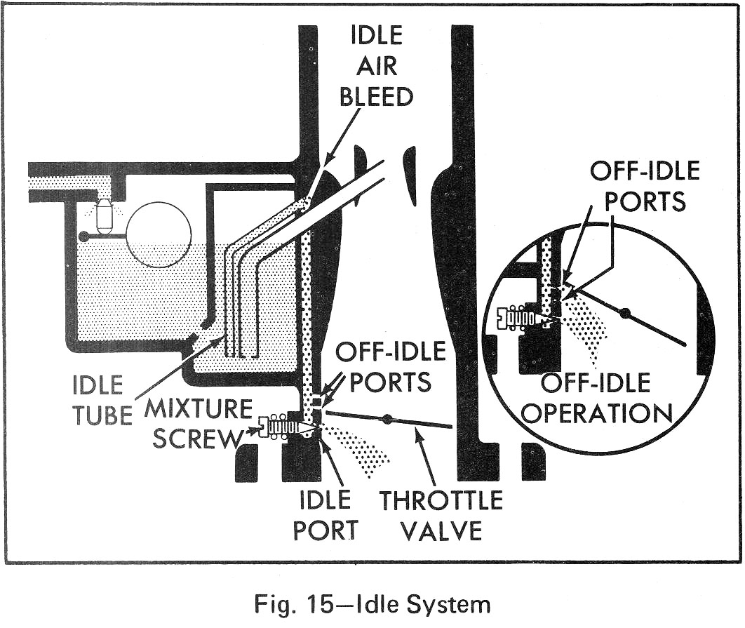
being nearly closed and is insufficient to meter fuel properly from the main discharge nozzle. To offset this condition, the idle system is used to provide the proper mixture ratios required during engine idle and low speed operation. The idle system consists of an idle tube, idle passages, idle air bleeds, off-idle discharge ports, idle mixture adjusting needle and the idle mixture needle discharge port.
In the idle speed position, the throttle valve is slightly open, allowing a small amount of air to pass between the wall of the carburetor bore and the edge of the throttle valve. Since there is not enough air flow for venturi action, the fuel is made to flow by the application of manifold vacuum directly through the idle system to the fuel in the carburetor bowl.
The low pressure below the throttle valve (manifold vacuum) will cause the fuel to flow through the idle tube, into the idle passage, where it is mixed with air from the air bleed. This is the first stage of atomizing the fuel. The mixture continues down the passage, past the off-idle ports. At this point these ports act as air bleeds to further break up the mixture.
The mixture flows past the mixture screw into the carburetor bore and into the engine intake manifold. The mixture screw controls the idle mixture and is turned in to lean the mixture and out to richen it. Mixture screws are now locked after flow test at the manufacturing plant by means of limiter caps which attach over the mixture screws. These caps must not be tampered with in the field due to the effect on exhaust emissions.
As the throttle valve is opened, additional air flows through the carburetor. Since air flow is still insufficient to draw fuel from the main nozzle, the increased air flow results in excessively lean mixtures. To compensate for this problem off-idle ports are added to the carburetor (inset Fig. 15) just above the closed throttle position. When the throttle is opened during slow speed or off-idle operation (Fig. 15), the off-idle ports are exposed to manifold vacuum and begin discharging extra fuel mixture for off-idle requirements. Thus, the off-idle ports have a dual purpose. At idle they act as air bleeds but during the off-idle range they change to fuel mixture feeds.
Both the idle and off-idle ports are designed to provide a smooth transition between idling and cruising speeds of 25 to 40 mph for passenger cars, depending on carburetor design. At these speeds, the throttle opening and air flow are sufficient to permit the main metering system to begin to supply fuel.
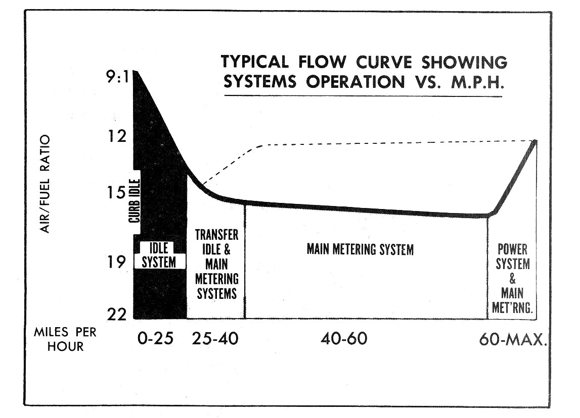 Fig. 16—Typical Systems Operation
The point at which fuel flow starts from the main nozzle is the transfer point (Fig. 16). This means that the carburetor is passing from idle to main metering system. The idle port discharge however, does not cease at this point but rather diminishes as main nozzle discharge increases. Thus, the two systems interact and produce a smooth fuel-air flow at all engine speeds.
 Main Metering System (Fig. 17)
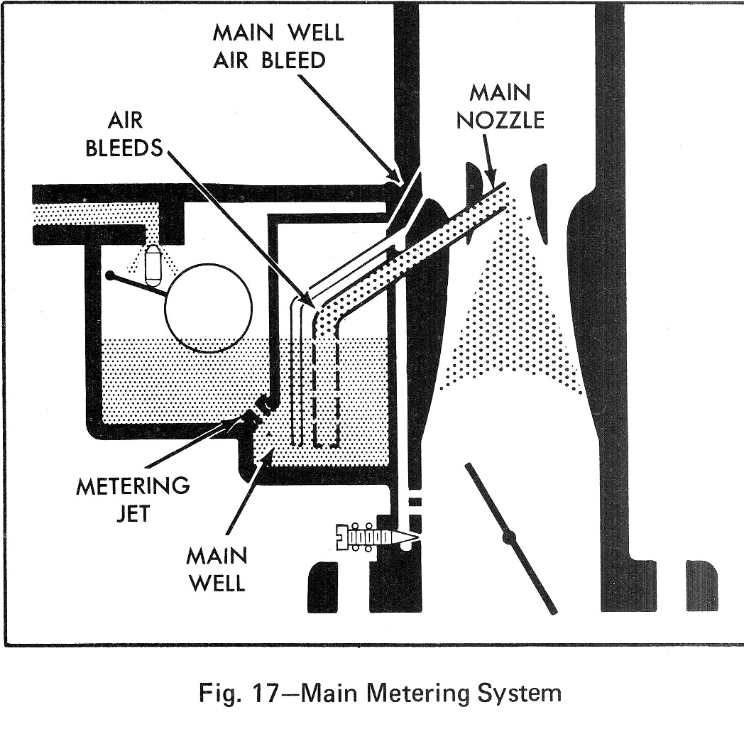
The main metering system controls the economy range of the carburetor. It consists of a main jet, main well and main nozzle with air bleeds in it. The main jet is a very accurately machined orifice, which controls the fuel flow through the main well in which the nozzle is located. An air bleed in the main well and the air bleeds in the main nozzle keep the mixture constant throughout the operating range of the main metering system.
As the throttle valve is opened, air velocity through the venturi system increases which in turn decreases the pressure in the venturi at the main fuel nozzle. This action causes the fuel to pass through the main metering jet into the main well where it rises in the main well passage and idle pickup tube. As the fuel enters the nozzle, it is mixed with air through calibrated holes in the nozzle. Air is bled into the main well by the air bleeds. This air aids in breaking up the fuel for improved distribution. The mixture continues through the main discharge nozzle and enters the air stream at the boost venturi. At this point it is mixed with the incoming air and is carried past the throttle valve and into the manifold for distribution to the engine cylinders.
The main metering jet and the air bleeds are pre-calibrated to maintain the desired air-fuel ratios throughout the main metering range. Therefore, no adjustments are necessary in the main metering system.
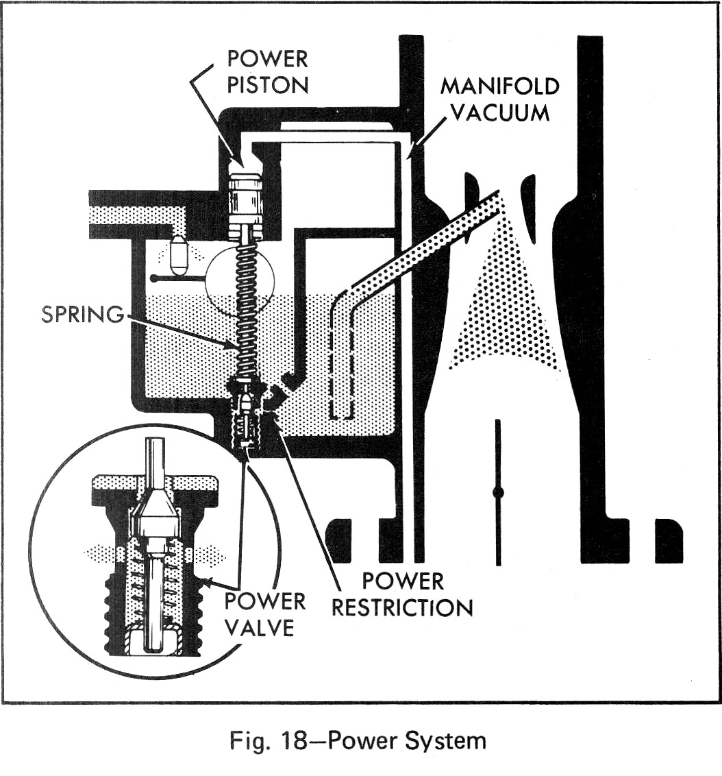
As discussed previously, richer fuel mixtures are needed for high speed operation since maximum engine power requires the use of all available air for combustion. The power system is used to supplement the main metering system and provide the power enrichment according to the amount of throttle opening and engine load. The power system consists of: a power valve, power piston and spring, and power restriction. The power valve controls a fuel passage which bypasses the main metering jet from the bowl to the main well.
The power piston is located above the valve and determines when the valve will open. The power piston is spring loaded and normally held in the closed position by high manifold vacuum conditions. Under conditions of power, manifold vacuum will be low which means vacuum will decrease on top of the piston allowing the spring to force the power piston down, opening the valve to increase the fuel flow to the main nozzle. This has the same effect as enlarging the main jet. A calibrated power restriction is used in the passage between the power valve and the main well to control the amount of enrichment. While this system is constantly operative only at speeds approaching wide open throttle and above, sudden throttle openings at slow and mid-range speeds will cause momentary opening of the power valve, due to resultant manifold vacuum decreases.
Power valve springs generally are calibrated to allow opening to begin at 8" to 9" average and full opening when manifold vacuum falls below 4" to 6" average. There is no adjustment required for the power system.
When the throttle is opened rapidly, the air flow and manifold vacuum change almost instantly. Because of the great difference in weight between air and fuel, any sudden change in throttle opening results in an immediate increase in air intake but the fuel, having greater weight tends to lag behind. The result of this is momentary leanness.
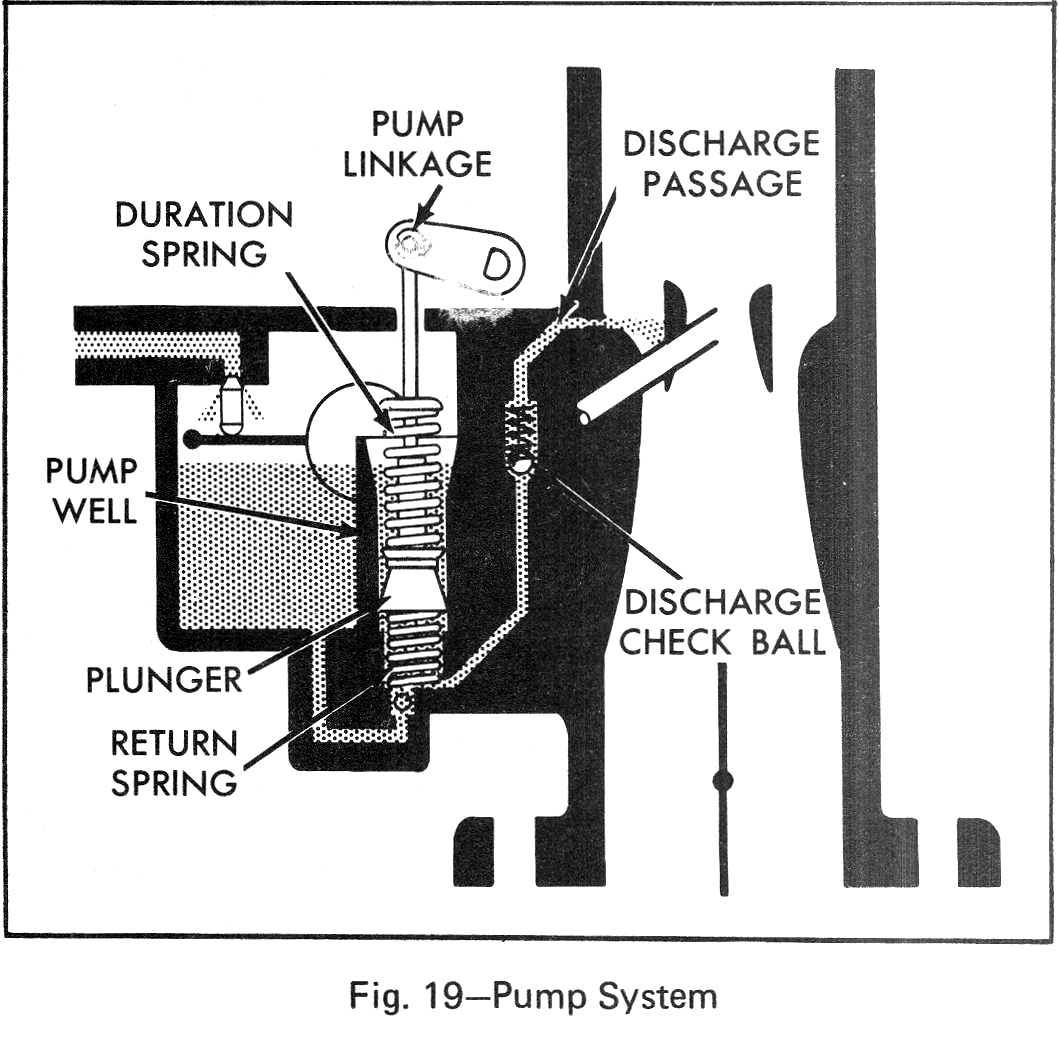
The accelerator pump provides the extra fuel necessary to overcome this leanness and give smooth operation during transient operations. This is accomplished by discharging extra fuel into the venturi air stream whenever the throttle valve is opened. The pump system utilizes a pump plunger that is linked to the throttle lever by mechanical linkage. When the pump plunger moves upward in the pump well, as happens during throttle closing, fuel from the float bowl enters the pump well through a slot in the top of the pump well, or through an inlet check valve in earlier design carburetors. It flows past the pump cup seal into the bottom of the pump well.
The pump plunger is the floating type of which the cup moves up and down on the pump plunger head. Some models may use the fixed cup, ball vapor vent design. When the pump plunger is moved upward, the flat on the top of the cup unseats from the flat on the plunger head and allows free movement of fuel through the inside of the cup into the bottom of the pump well. During a shut down soak period this also vents any vapors which may be in the bottom of the pump well so that a solid charge of fuel can be maintained in the fuel well beneath the plunger head. At the same time, the discharge check valve seats to prevent air from leaking into the discharge passage.
When the throttle valves are opened, the connecting linkage forces the pump plunger downward. The pump cup seats instantly and fuel is forced through the pump discharge passage, where it unseats the pump discharge check valve and passes on through the passage to the pump jets where it sprays into the venturi area of each bore. The accelerator pump system is an accessory device which has no function other than momentary operation at the time of throttle position changes. The pump is purely mechanical and not affected by air flow.
Choke System (Fig. 20)
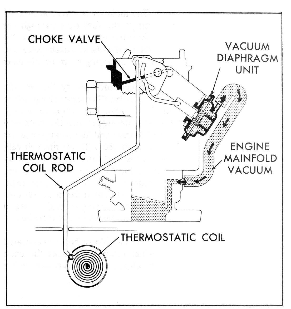
The necessary requirements for good fuel vaporization are missing or are inadequate when starting a cold engine. To overcome this condition, plus condensation of the fuel on the cold manifold, it is necessary to meter extremely rich mixtures from the carburetor (2:1 to 1:1 air-fuel ratios) in order to provide sufficient combustible mixtures to the cylinders for quick starting. This enrichment is obtained by the addition of a choke valve in the air horn above the main venturi. When the choke valve is closed during engine cranking, very little air is allowed to enter the carburetor and manifold vacuum is applied directly to the idle and main metering system; starting fuel to flow through these systems. The choke system consists of a choke valve located in the primary air horn, a vacuum break diaphragm unit, fast idle cam, choke linkage and a thermostatic coil which is located on the engine manifold. The coil is connected to the choke valve by a rod.
The choke operation is controlled by a combination of intake manifold vacuum, the off-set choke valve, thermostatic coil characteristics, atmospheric temperature, and exhaust manifold heat. The remote thermostatic coil located on the engine manifold is calibrated to hold the choke valve closed when starting a cold engine, air velocity against the off-set choke valve causes the valve to open slightly, against the torque of the thermostatic coil.
When the engine is started, manifold vacuum applied to the vacuum diaphragm unit mounted on the carburetor air horn will open the choke valve to a point where the engine will operate without loading (rich) or stalling (lean). The choke valve will remain in this position until the engine begins to warm up. Through application of exhaust manifold heat, the thermostatic coil relaxes gradually until the choke valve is fully open.
Opening of the choke valve is controlled by air flow through the carburetor air horn, past the off-set choke valve and manifold heat acting upon the thermostatic coil. As the engine is accelerated during warm-up, the corresponding drop in manifold vacuum and low air flow against the off-set choke valve, allows the thermostatic coil to momentarily close the choke, providing a richer mixture.
During warm-up it is necessary to provide a faster idle to prevent engine stalling. This is accomplished by a fast idle cam which is connected by a rod to a lever on the choke shaft. The idle screw on the throttle lever contacts graduated steps on the fast idle cam to provide a faster idle than normal, to prevent engine stalling during the warm-up period. When the engine is fully warm and the choke valve is wide open, the fast idle cam rotates so that the idle screw rests on the low step on the fast idle cam where normal curb idle is obtained. Some carburetors have separate fast and curb idle air adjustment screws.
If the engine becomes flooded during the starting period, the choke valve can be partially opened manually to allow increased air flow through the carburetor. This is accomplished by depressing the accelerator pedal to the floor. The unloader projection on the throttle lever contacts the edge of the fast idle cam and, in turn, partially opens the choke valve. The extra air leans out the fuel mixture enough so the engine will start.