previous page: High Speed and Power System
PUMP CIRCUIT

The pump circuit is incorporated in the downdraft carburetor, for the purpose of injecting a stream of raw gasoline into the air stream flowing in the air horn and throat of the carburetor, when changing from low to high speed for rapid acceleration. This is why it is termed "accelerating pump circuit".
Since most accelerating pump systems are of the same general construction, locating trouble is not too difficult a problem in this part of the carburetor.
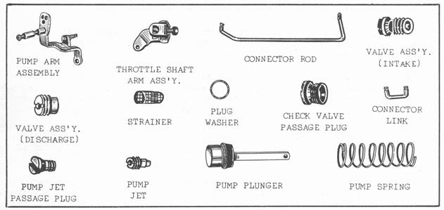
The pump circuit consists of the following: pump cylinder, pump plunger, plunger operating rod, plunger spring, intake check valve, outlet check valve and pump jet. As the throttle is closed, the linkage raises the pump plunger in the cylinder. When the throttle valve is opened the pump plunger is forced down, the inlet check valve seats itself and the pressure on the fuel opens the discharge check valve and the gasoline flows through the pump jet into the throat of the carburetor. By using a small orifice or opening in the pump jet, the pressure in the pump system is increased so that a full steady stream of fuel will flow, depending on the amount of throttle shaft travel. This metering orifice in the pump jet also controls or measures the size of the stream of fuel, flowing out of the pump system into the throat of the carburetor.
The usual complaint when the accelerating pump circuit goes bad or becomes defective, is a noticeable "flat spot" when trying to start from a complete standstill or a hesitation on acceleration. A quick check can be made as follows: With the engine stopped, remove the air filter. Look down inside throat of the carburetor. Open throttle by hand, slowly at first and then quickly. Watch for stream of gas coming from pump jet. It should be a steady full stream from the start to finish of throttle travel. If the stream of gas is not full and steady, remove the carburetor and completely check pump circuit.
Some causes of a faulty or inoperative pump system are the following: a worn pump plunger, one that the leather seal has become hardened or cracked, or one that was damaged when it was inserted in the pump cylinder. As the plunger travels down in the cylinder, the fuel goes past the plunger piston instead of being forced out through the pump jet, because the leather does not seal properly against the cylinder wall. A worn or bent pump operating linkage, leaking check valves, a restricted pump jet, or a collapsed or wrong size plunger spring, will definitely cause trouble in the pump circuit.
On some Stromberg carburetors it is often a case of the small pump link coming out of the hole in the pump plunger rod. To overcome this condition install the new type link which is longer on one end. The long end goes into the pump operating rod. In late model Ball & Ball carburetors the intake and discharge ball check seats are part of the body casting. Two steel balls are used as the check valves. The discharge ball (one under brass plug) is larger than the ball located in the base of the pump cylinder.
A peculiar condition will sometimes occur, whereby after installing a new pump plunger and thoroughly cleaning the pump section a flat spot is still present. In other words, insufficient gas is going through the pump circuit. This condition can often be corrected, by placing a ball which is the same size as the ball in the pump cylinder in place of the larger ball under the brass plug. The small ball fits deeper into the discharge valve seat and makes a better seal.
The Chevrolet Carter Carburetor has a direct acting pump system and is not vented. If the pump jet becomes clogged or restricted, when the throttle is operated, the pump connector rod will bend and being bent will hold the throttle open causing the engine to race. Naturally with a restricted pump circuit a decided flat spot will result.
On other Carter carburetors the pump system is vented to the outside. This prevents any serious damage to the pump system in case of a clogged jet.
On all WA-1 Carter carburetors the pump is vented to the outside and some units use a spring loaded countershaft arm as a safety device in the pump operating linkage.
On the Stromberg, Ball & Ball and some Zenith carburetors a delayed action pump is used. There is no physical connection between the pump plunger and the plunger operating rod, other than the rod exerts pressure on the pump spring and the spring in turn forces the plunger down in the cylinder against the fuel. This is what is known as a delayed action pump circuit. As the spring is mounted on top of the plunger, if the pump system becomes plugged no damage will be done to it.
next: Choke Circuit
Table of Contents
The Carburetor and Its Purpose
- Carburetor Construction and Circuits
- Float Circuit
- Low Speed Circuit
- High Speed and Power System
- Pump Circuit
- Choke Circuit
- Anti-Percolation
- Dual Carburetors
- Low Speed Circuit
- High Speed Circuits
- Pump Circuit
- Choke Circuit
- Compound Carburetion
Tune-Up of the Gasoline Engine
- Compression
- Ignition
- Carburetion
- Short Cuts in Trouble Shooting
- Vacuum Gauge Tests While Engine Is Running
- Correct Setting of Ignition Timing With Vacuum Gauge
- Instructions for Use and Purpose Of Compression Gauge
- Testing the Ignition Circuit
- How to Make Test With Analyzer
- Procedure of Test
- Road Testing
